


+86-15339975475
info@archeanref.com
info@archeanref.com
+8615339975475
Wutongli, linyi, Shandong, China


Views: 0 Author: Site Editor Publish Time: 2026-08-29 Origin: Site


Refrigeration system design forces a fundamental engineering choice. You must weigh the absolute prevention of refrigerant leaks against the convenience of on-site repairability. Every mechanical cooling setup faces this exact tension. Eliminating escape routes for volatile gases often means locking components away permanently.
To resolve this, engineers turn to a specific sealed architecture. This design remains the industry standard for specific commercial and residential cooling applications where zero-leakage and low maintenance are non-negotiable. It protects internal mechanisms from ambient conditions and unauthorized tampering. Systems demanding high reliability simply cannot rely on exposed moving parts.
Selecting the right compressor architecture requires understanding its internal mechanics and long-term performance. You must evaluate how the unit handles thermal loads under continuous operation. We will explore how this sealed structure operates and how it compares to semi-hermetic alternatives. This knowledge ensures you make an informed decision for your next system deployment.
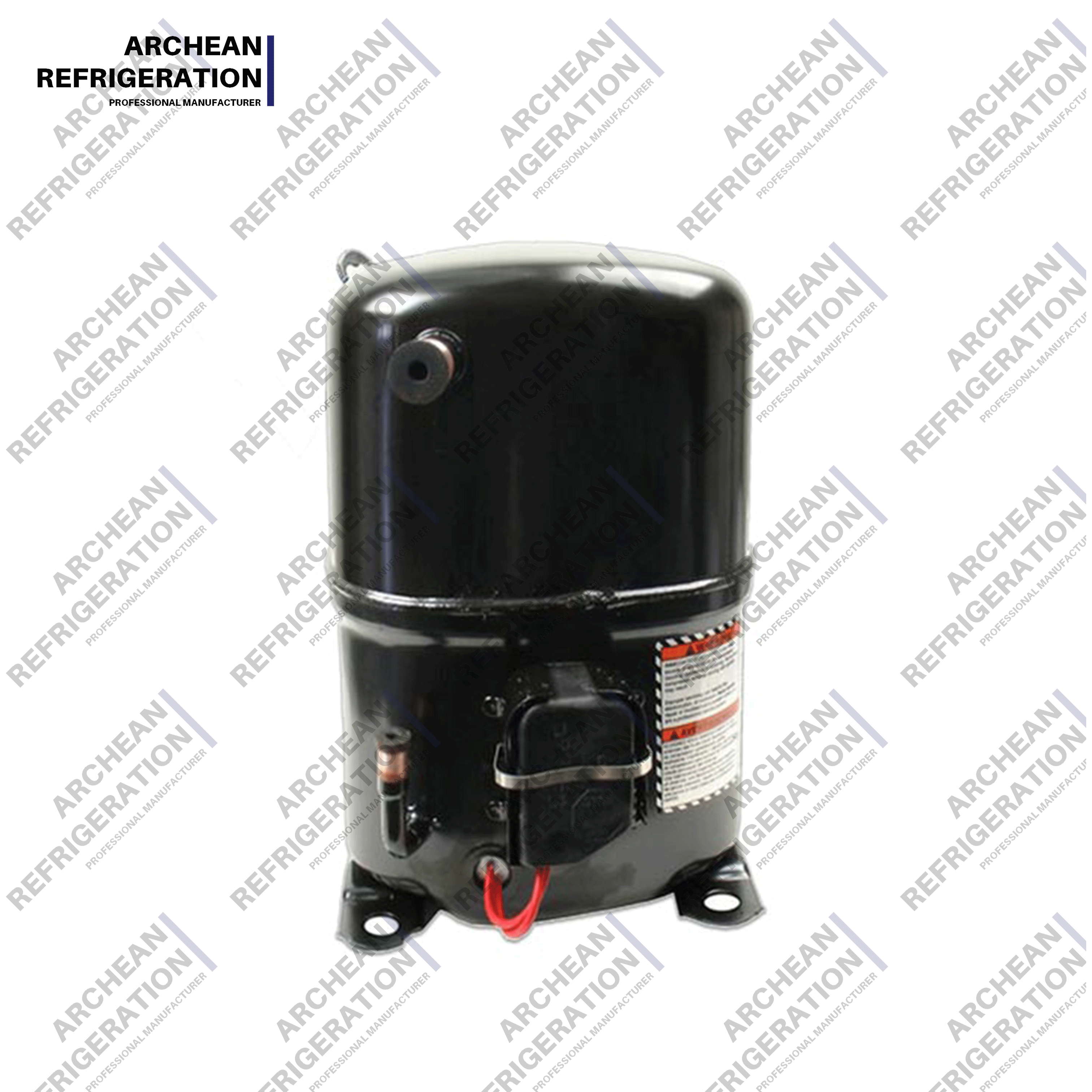
A hermetic compressor seals both the electric motor and the compressor mechanism within a single, welded steel casing, entirely eliminating the need for a shaft seal.
Its primary advantage is the prevention of refrigerant leaks, making it highly reliable and virtually maintenance-free.
The major limitation is non-repairability; internal mechanical or electrical failures require complete unit replacement.
Ideal applications include systems with strict space, noise, and low-maintenance constraints where capital expenditure (CapEx) takes precedence over lifetime repairability.
The defining structural feature of this unit is its heavy-duty welded steel shell. Manufacturers encase the entire electro-mechanical assembly inside this impenetrable cylinder. They directly couple the electric motor and the compression mechanism on a single, shared shaft. This direct-drive integration eliminates external belts, gears, or exposed rotating components. Everything remains suspended securely on internal spring mounts to absorb vibrations.
This closed-shell design delivers massive business value by entirely eliminating shaft seals. Traditional open-drive models require a physical shaft to protrude through the exterior casing to connect to an external motor. These shaft seals constantly undergo mechanical wear and thermal stress. They represent the single most common failure point for leaks in standard open systems. By removing the shaft seal, a refrigeration compressor achieves an incredibly tight, leak-proof operational envelope. Facilities save thousands of dollars annually by avoiding lost refrigerant replacement and environmental fines.
However, this sealed environment creates a unique thermal management challenge. Because the motor sits locked inside a steel vault, it cannot rely on ambient air or external cooling fans. The internal electric motor relies entirely on the suction gas flowing over it to prevent overheating. As cold, low-pressure refrigerant returns from the evaporator, it sweeps across the copper motor windings. It absorbs waste heat before entering the compression cylinder. This cooling dependency is a critical factor for system longevity. If the system suffers a low refrigerant charge, the motor will rapidly overheat, degrading the winding insulation and risking a severe electrical short.
Understanding the internal workflow reveals why this design achieves such high reliability. The cycle relies on precise fluid dynamics and thermodynamic principles. We can break down the operation of a hermetic refrigerant compressor into three distinct mechanical phases, followed by continuous lubrication management.
Phase 1: Suction and Motor Cooling
The cycle begins when low-pressure refrigerant vapor enters the steel shell from the suction line. Instead of flowing directly into the compression chamber, this cold gas first acts as a coolant. It passes vigorously over the motor stator and rotor windings. The vapor dissipates massive amounts of electrical waste heat generated by the running motor. This heat exchange slightly warms the incoming gas, raising its temperature just before it enters the intake valves of the cylinder.
Phase 2: The Compression Cycle
Once the gas navigates past the motor, it enters the compression mechanism. Depending on the specific design, this involves either a reciprocating piston or a rotary scroll mechanism. The mechanism physically traps a specific volume of the low-pressure gas. It mechanically forces the gas into a progressively smaller space. This rapid volume reduction fundamentally alters the state of the gas. It rapidly increases both the pressure and the temperature, preparing the refrigerant to reject heat downstream in the condenser.
Phase 3: Discharge
The now high-pressure, high-temperature gas forces its way through the discharge valve assembly. Before it leaves the shell, it typically travels through an internal discharge muffler. This muffler smooths out the violent pressure pulsations created by the pistons or scrolls. Finally, the hot gas exits the compressor shell through the discharge line and travels directly to the condenser coil to release its accumulated heat.
Underpinning these three phases is an intricate lubrication management system. Moving metal parts running at thousands of revolutions per minute require constant oiling. The bottom of the welded shell serves as a dedicated oil sump. A small mechanical oil pump, or sometimes a simple centrifugal flinger attached to the bottom of the crankshaft, continuously draws oil upward. It forces the lubricant through internal channels machined directly into the shaft. This distributes oil to the main bearings, connecting rods, and cylinder walls. Because the system is entirely enclosed, the lubrication functions as a true closed-loop process. The oil never degrades from atmospheric exposure or external moisture contamination.
Choosing the right architecture requires balancing upfront costs, maintenance capabilities, and physical footprint. Facility managers generally evaluate three primary configurations. Each presents specific trade-offs regarding serviceability and leak prevention.
Hermetic (Welded): These units offer zero routine maintenance requirements and the lowest initial purchasing cost. They feature a highly compact footprint and naturally quiet operation. Trade-off: You face 100% replacement upon failure. You cannot open the shell to replace a broken valve or a burnt motor winding.
Semi-Hermetic (Bolted): This design places the motor and compressor in a shared cast-iron housing, but seals them with heavy bolted, gasketed covers. They provide excellent leak resistance while remaining accessible. Trade-off: They carry a significantly higher initial cost and demand a larger footprint. However, they are fully rebuildable and repairable on-site by skilled technicians.
Open Drive: The motor and compressor remain entirely separate components. They connect externally via a belt drive or a direct mechanical coupling. Trade-off: They carry the highest risk of refrigerant leaks directly at the protruding shaft seal. They require rigorous preventative maintenance and alignment checks. Engineers typically reserve these for specialized, heavy industrial applications like massive ammonia plants.
You need a structured shortlisting logic to guide procurement. A simple matrix helps isolate the correct technology based on capacity and operational priorities. Choose a hermetic compressor for sub-30 horsepower applications where prioritizing a small footprint and low initial cost is paramount. Choose a semi-hermetic unit for high-capacity commercial systems where minimizing complete replacement downtime is critical for business continuity.
| Architecture Type | Leak Prevention | On-Site Repairability | Initial Cost | Typical Application Range |
|---|---|---|---|---|
| Welded Hermetic | Excellent | None (Replace Only) | Low | Residential & Light Commercial |
| Bolted Semi-Hermetic | Very Good | High | Medium to High | Commercial Supermarkets & Cold Storage |
| Open Drive | Poor (Shaft Seal Risk) | Very High | Very High | Heavy Industrial & Chemical Plants |
When engineering a cooling loop, specifying the compressor involves far more than matching horsepower. You must evaluate several technical performance metrics to ensure long-term stability.
Capacity and application limits dictate the initial boundary. Manufacturers typically design welded units for light-to-medium loads. You will commonly find them in household refrigerators, window air conditioners, retail display cases, and rooftop HVAC packages. They usually max out around 30 to 40 horsepower. They simply aren't suited for massive industrial refrigeration plants. High-capacity industrial systems generate immense internal heat that a suction-cooled, enclosed motor struggles to dissipate effectively. Furthermore, the sheer physical size of a welded shell for a 100-horsepower system would make manufacturing and transportation unviable.
Coefficient of Performance (COP) and thermodynamic efficiency require careful calculation. You must evaluate the electrical energy draw versus the actual cooling output. Because the suction gas cools the internal motor, the motor inevitably adds heat to the refrigerant before compression even begins. This added heat expands the vapor, slightly decreasing the volumetric efficiency of the cylinders. Engineers must factor this motor heat penalty into their COP calculations when comparing enclosed systems against open-drive alternatives.
Acoustic and vibration profiles often finalize the procurement decision. The heavy steel welded shell acts as a natural, highly effective acoustic dampener. It traps mechanical noise and suppresses the high-frequency whine of the electric motor. Internal spring suspensions further isolate the moving parts from the external casing. This makes the sealed type vastly superior for noise-sensitive environments. You will almost exclusively see them specified for retail sales floors, hospitality venues, and hospital environments where mechanical noise disruptions are unacceptable.
Despite their stellar reliability, these units require a pragmatic operational strategy. You must understand the constraints of a system you cannot open.
Operators must accept the "run-to-fail" reality. There is absolutely no internal preventative maintenance you can perform. You cannot inspect the bearings, clean the oil strainer, or adjust the valves. Instead, facility teams must rely on monitoring external metrics. You track electrical current draw, discharge temperatures, and suction pressures. A sudden spike in amperage or an unexplainable drop in cooling capacity serves as your only warning that internal mechanical wear has reached a critical threshold.
Handling motor burnouts represents the most severe risk scenario. If the system suffers a prolonged low-voltage event, a locked rotor, or a loss of refrigerant charge, the internal windings will rapidly overheat. The insulation melts, and the motor shorts out. This electrical failure inside the shell violently carbonizes the oil and vaporizes the insulation. It contaminates the entire refrigerant loop with highly acidic, toxic byproducts. A burnout transforms a simple mechanical failure into a system-wide chemical contamination event.
The replacement protocol following a burnout requires extreme rigor. You cannot simply braze in a new unit and walk away. The highly acidic sludge left in the piping will immediately attack the insulation of the replacement motor, causing a secondary burnout within weeks. Technicians must perform extensive system flushing using specialized chemical solvents. They must conduct chemical acid testing on the remaining oil. Finally, they must install oversized liquid-line and suction-line filter-driers. These driers scavenge any residual acid and particulate matter, ensuring the new compressor operates in a chemically neutral environment.
The hermetic compressor stands as a masterclass in intentional engineering limitation. By intentionally trading away on-site serviceability, manufacturers deliver absolute leak prevention, silent operation, and mechanical simplicity. It remains the undisputed choice for environments prioritizing cleanliness, compactness, and low upfront costs over lifetime repair flexibility.
Technical buyers and facility managers should actively audit their current cooling loads before specifying a replacement. Assess your physical footprint constraints. Evaluate your actual tolerance for equipment downtime. If a failure means losing thousands of dollars in perishable inventory, you must weigh the speed of swapping a sealed unit against the rebuild time of a semi-hermetic model.
Do not finalize your system architecture in isolation. Consult directly with an application engineer to properly size your next replacement. They can analyze your thermal demands and acoustic requirements. Explore the latest product catalogs to match specific capacity ranges with highly efficient, modern sealed designs.
A: No. Because the heavy steel casing is permanently welded shut at the factory, accessing the internal components for repair is impossible without cutting the shell open. Cutting the steel destroys its structural integrity and pressure-holding capability. When internal parts fail, the entire unit must be replaced.
A: Typically 10 to 15 years. However, this lifespan is heavily dependent on proper initial system installation, maintaining consistent electrical voltage, and ensuring it constantly operates within its designed thermal limits without losing refrigerant charge.
A: They rely exclusively on cold returning suction gas for motor cooling. Overheating usually occurs due to a low refrigerant charge caused by leaks elsewhere in the system. It can also happen due to restricted airflow over the condenser coils or severe electrical voltage imbalances.


