


+86-15339975475
info@archeanref.com
info@archeanref.com
+8615339975475
Wutongli, linyi, Shandong, China


Views: 0 Author: Site Editor Publish Time: 2026-08-17 Origin: Site


Commercial cooling relies on a central mechanical engine. System efficiency depends heavily on this device. It drives energy consumption and operational reliability in industrial settings. Many view it simply as a metal component. However, it represents the primary driver of thermal management. You must understand its internal functions to optimize cooling performance. Facilities face strict compliance mandates and changing load demands. Evaluating these variables requires deep mechanical insight. We will explore how these systems manipulate gas pressures. You will learn the mechanical differences between various equipment architectures. This knowledge helps you align hardware choices with specific facility requirements. Decision-makers can then select the most appropriate technology. Poor equipment selection leads to massive energy waste and frequent breakdowns. We aim to bridge the gap between thermodynamic theory and practical procurement.
The fundamental role of a refrigeration compressor is to raise the pressure and temperature of a low-pressure gas, forcing heat exchange within the broader refrigeration cycle.
Different mechanical approaches (scroll, screw, reciprocating, centrifugal) directly dictate a system’s scalability, part-load efficiency, and maintenance requirements.
Selecting the right compressor requires balancing initial capital expenditure against long-term energy costs, refrigerant compatibility (GWP regulations), and specific application demands.
Proper oil management and avoiding liquid slugging are critical operational realities for maximizing compressor lifespan.
Physics dictates how heat moves. Heat naturally flows from warmer areas to cooler areas. We must reverse this natural flow to achieve commercial cooling. A compressor forces this reversal. It takes low-pressure, low-temperature vapor from the evaporator coil. The machine then physically squeezes this gas into a smaller volume. This action drastically increases the pressure and temperature of the vapor. High pressure ensures the gas becomes hotter than the outside ambient air. Heat can then reject effectively into the surrounding environment.
The compressor never operates in isolation. It anchors a continuous closed-loop sequence. We can break this sequence into four distinct stages.
Evaporation: Liquid boils into a vapor. It absorbs ambient heat from the target space.
Compression: The unit draws in the warm vapor. It increases pressure and temperature to enable future heat rejection.
Condensation: The superheated gas enters the condenser coil. It releases absorbed heat into the outside air or water loop. The gas condenser back into a high-pressure liquid.
Expansion: A metering device abruptly drops the liquid pressure. This rapid pressure drop cools the liquid. It prepares the fluid to restart the cycle.
You can compare a cooling circuit to the human circulatory system. The piping represents the veins and arteries. The chemical fluid acts as the circulating blood. In this analogy, the refrigerant compressor serves as the beating heart. It provides the mechanical force required to push the fluid through the circuit. Without this driving force, the fluid would stagnate. The entire heat exchange process would immediately halt.
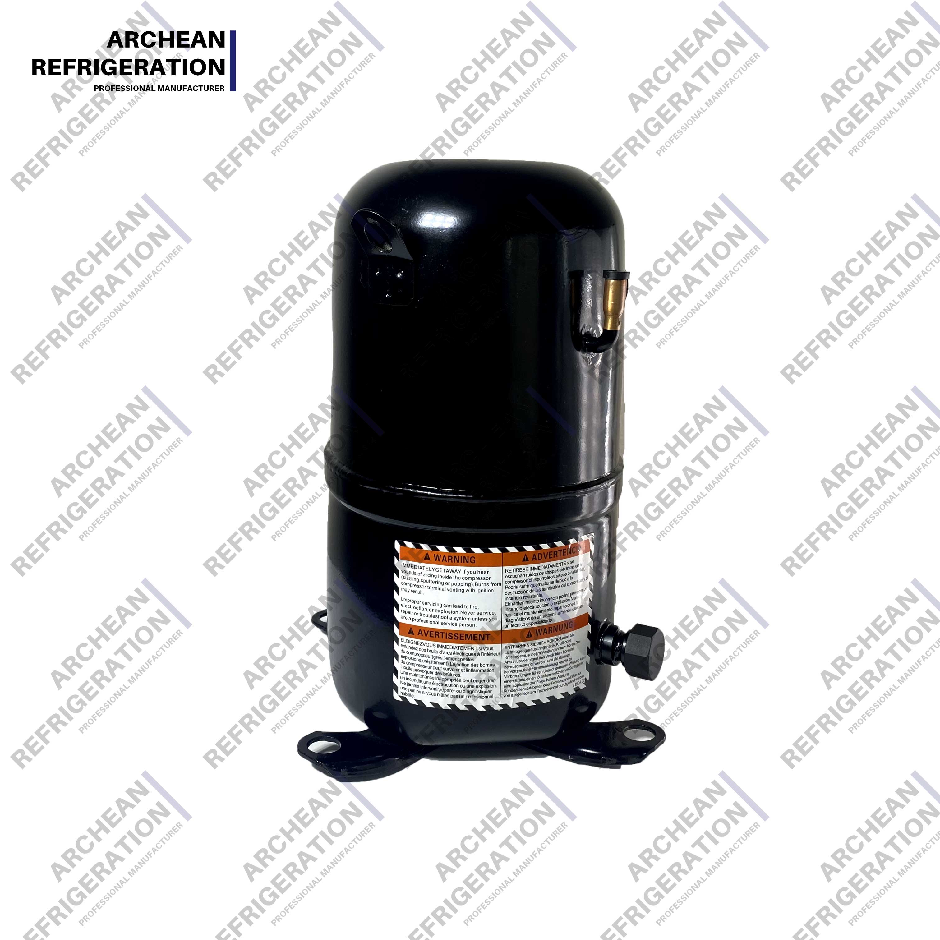
Manufacturers design various mechanisms to achieve the same thermodynamic goal. Different load profiles require different physical approaches. We must break down these physical mechanisms. This helps map them to their ideal commercial use cases.
A reciprocating unit utilizes familiar internal combustion engine mechanics. It relies on a crankshaft-driven piston moving inside a rigid cylinder. The downward stroke opens a suction valve. This draws low-pressure gas into the cylinder chamber. The upward stroke forces the suction valve closed. The rising piston compresses the trapped gas. Pressure builds until it overcomes the discharge valve spring. The hot gas then pushes out into the discharge line.
These units remain highly durable. Technicians can easily rebuild semi-hermetic models in the field. They handle variable refrigeration loads exceptionally well. Supermarkets heavily rely on them for diverse temperature zones. However, the reciprocal motion creates distinct challenges. They generate significant vibration. They also produce more noise than rotary alternatives. You must account for acoustics during installation.
Scroll technology dominates modern mid-range cooling. The mechanism uses two interleaved spiral vanes. One scroll remains completely stationary. The other scroll orbits around the stationary one. It does not rotate on its own axis. This orbital motion creates crescent-shaped gas pockets. The pockets continuously move toward the center of the scroll set. The volume of the pocket decreases as it moves inward. Gas reaches maximum pressure at the central discharge port.
This design eliminates traditional suction and discharge valves. Fewer moving parts translate directly to higher mechanical reliability. Scroll units operate quietly. They generate minimal vibration. You will find them primarily in commercial HVAC compressor applications. They also serve medium-temperature refrigeration perfectly. They offer excellent volumetric efficiency across varied conditions.
Heavy-duty industrial cooling requires continuous high-volume displacement. Screw compressors excel here. They trap incoming gas between two meshing helical rotors. We call these the male and female rotors. A motor drives the male rotor. The male rotor turns the female rotor. Gas enters one end of the cylinder. The rotating threads reduce the internal volume. They physically force the gas down the length of the rotors.
These units handle massive commercial chillers effortlessly. They provide exceptional efficiency at full load conditions. Internal slide valves allow precise capacity control. This means they can modulate output to match building loads. However, they require highly precise oil management. Oil injects directly into the rotors. It seals the clearances between the metal threads. It also cools the gas during compression. Loss of lubrication causes immediate catastrophic failure.
Centrifugal models abandon positive displacement entirely. They rely strictly on kinetic energy. A high-speed rotating impeller draws gas into its center. The spinning blades violently accelerate the gas outward. The gas leaves the impeller at massive velocity. It then enters a stationary component called a diffuser. The diffuser abruptly slows the gas down. Physics converts this sudden drop in velocity into a massive spike in static pressure.
Facility managers specify them for massive enterprise thermal management. Large district cooling plants and high-rise buildings depend on them. They move enormous volumes of vapor. They achieve peak efficiency at full capacity. However, they suffer from a phenomenon called surging. Surging occurs under low-load conditions. The pressure difference causes gas to flow backward through the impeller. This violent reversal can destroy the bearings.
Table 1: Compressor Architecture Comparison Matrix
| Compressor Type | Primary Mechanism | Best Commercial Application | Operational Weakness |
|---|---|---|---|
| Reciprocating | Crankshaft and piston inside a cylinder | Supermarkets, variable temp zones | High vibration and noise output |
| Scroll | Orbiting and stationary interleaved spirals | Light commercial AC, mid-temp retail | Hermetically sealed; cannot be field rebuilt |
| Screw | Twin meshing helical rotors | Industrial process cooling, large chillers | Complex oil injection and separation needs |
| Centrifugal | High-speed rotating impeller and diffuser | Massive enterprise plants, district cooling | Prone to surging under low-load conditions |
Raw power rarely equals practical efficiency. You must evaluate how equipment performs under actual building conditions. Facilities rarely operate at peak design conditions year-round. Therefore, full-load efficiency metrics tell an incomplete story. Industry standards utilize Integrated Part Load Value (IPLV). IPLV measures efficiency across various partial capacity states. It provides a highly accurate reflection of real-world energy use.
Matching the system output to the immediate thermal demand is vital. Fixed-speed units turn on at full blast. They shut off completely when the temperature drops. This on-off cycle wastes massive amounts of electricity. Modern facilities utilize Variable Frequency Drives (VFDs). A VFD alters the electrical frequency supplied to the motor. It allows the machine to speed up or slow down smoothly. This continuous modulation matches the real-time cooling load perfectly. It drastically reduces energy consumption.
Global environmental regulations dictate hardware choices today. The Environmental Protection Agency (EPA) actively phases down high-GWP (Global Warming Potential) hydrofluorocarbons. You cannot specify equipment based solely on mechanical preference. The hardware must handle next-generation chemicals.
Many facilities pivot toward natural options like CO2 or Ammonia. These chemicals drastically alter mechanical requirements. CO2 systems operate at extraordinarily high pressures. A transcritical CO2 refrigeration compressor requires much thicker casing walls. It needs specialized safety relief valves. Ammonia offers incredible thermodynamic efficiency. However, it reacts violently with copper. Ammonia systems require steel-only piping and specific open-drive architectures. You must verify chemical compatibility before purchasing any hardware.
Spatial constraints influence equipment selection heavily. Urban facilities often lack sprawling mechanical rooms. A tight footprint demands compact rotary or scroll units. You must assess how much floor space the complete package requires. Clearances for maintenance access remain non-negotiable.
Acoustic requirements vary wildly by sector. A hospital cannot tolerate structural vibration. A data center might prioritize raw output over noise levels. Reciprocating units require heavy concrete inertia bases and spring isolators. Scroll systems might only need basic rubber mounting pads. Facility design must incorporate sound-attenuating enclosures if the chosen architecture operates loudly.
Mechanical failure happens quickly if physical realities are ignored. Compressors only pump vapor. They cannot pump liquid. Liquid molecules do not compress. Liquid slugging occurs when raw liquid refrigerant enters the suction port. The internal mechanics attempt to compress the incompressible fluid. This action shatters valves. It snaps connecting rods. It destroys scroll plates.
You mitigate this via strict system design. Engineers install suction line accumulators. An accumulator acts as a holding tank before the suction inlet. It boils off residual liquid before it causes damage. Technicians must also maintain proper suction superheat. Superheat guarantees the chemical has entirely transitioned into a vapor state. Routine checking of expansion valve settings prevents liquid flood-back.
Metal surfaces grinding against each other generate destructive friction. Continuous oil circulation prevents this wear. Oil travels through the circuit alongside the chemical vapor. The system must carry this oil back to the crankcase continuously. Failure to return oil leads to seized bearings.
Long vertical piping runs create specific risks. Oil struggles to travel upward against gravity. Installers must braze oil traps into vertical risers. Variable speed applications pose another risk. When the motor slows down, vapor velocity drops. Low velocity fails to push the heavier oil droplets through the pipes. System designers must install active oil separators. These devices strip oil from the discharge line and route it directly back to the sump.
You must understand the facility's unique rhythm. Cooling demands fall into two broad categories. Some environments require constant cooling. Industrial plastic injection molding runs 24 hours a day at exact temperatures. This constant demand favors robust screw machines. They run efficiently at fixed, continuous loads.
Comfort cooling experiences highly variable loads. Office buildings heat up at noon and cool down at midnight. These environments require highly adaptable machines. VFD-equipped scroll or reciprocating setups handle these swings effectively. You must map the peak demand against the baseline average demand.
Proper sizing dictates equipment survival. Many buyers instinctively choose larger units for safety margins. Oversizing causes extreme mechanical stress. An oversized machine rapidly satisfies the thermostat. It shuts off quickly. It turns back on minutes later. We call this short-cycling. Short-cycling burns out electrical contactors. It destroys motor windings. It prevents proper oil return.
Undersizing creates different problems. An undersized unit runs constantly. It never reaches the target temperature. The continuous operation overheats the internal motor. You must match the capacity directly to the calculated heat load.
Avoid making specification decisions based solely on catalog ratings. Engage an experienced mechanical engineer. They will run a comprehensive thermal load analysis. They will map the building envelope, internal heat gains, and local climate data. You should also demand an energy audit. The audit compares variable speed options against fixed-speed baselines. Let the mathematical data drive your final specification.
Understanding the internal workings of this equipment forms the baseline for operational success. You cannot separate the thermodynamic theory from the physical hardware. Different architectures manage gas pressures using entirely unique mechanisms. Piston, scroll, screw, and centrifugal designs all serve distinct load profiles.
There is no universal best option available on the market. You only find the most mathematically and mechanically appropriate choice for your specific facility. Protect your investment through rigorous oil management. Defend against liquid slugging through precise superheat controls. Partner with qualified system designers to ensure accurate capacity matching.
A: A failure causes an immediate system shutdown. The facility loses all cooling capacity. Internal mechanical destruction often scatters metal debris and acidic oil throughout the refrigerant lines. Technicians must perform extensive system flushes to remove contaminants. You must strictly diagnose and fix the root cause, such as low airflow or incorrect superheat, before installing a replacement.
A: It depends heavily on the architecture. Manufacturers completely weld hermetic models shut. You cannot open them; they require full replacement. Semi-hermetic and open-drive models feature bolted cast-iron housings. Qualified technicians can unbolt these units in the field. They can rebuild internal valves, pistons, and stators without discarding the entire machine.
A: Continuous operation indicates the system cannot absorb enough heat to satisfy the thermostat. A low refrigerant charge severely reduces cooling capacity. Blocked condenser coils prevent the system from rejecting heat outdoors. Alternatively, the unit might simply be undersized for the current ambient heat load. All these factors force the machine to run endlessly.


