
English 
+86-15339975475
info@archeanref.com
info@archeanref.com
+8615339975475
Wutongli, linyi, Shandong, China


Views: 0 Author: Site Editor Publish Time: 2026-10-14 Origin: Site


Is your commercial cooling unit shutting down for no obvious mechanical reason? HVAC/R technicians and facility managers often find themselves chasing phantom issues when a system repeatedly fails. Mechanical wear and tear usually take the blame. However, a silent electrical killer—voltage imbalance—is frequently the true culprit hiding in plain sight. This comprehensive guide explores exactly what causes this electrical asymmetry. We will break down the warning signs, such as excessive thermal stress and nuisance shutdowns. You will also find actionable, field-tested steps to calculate, diagnose, and permanently resolve the anomaly.
Voltage asymmetry occurs when the potential across the three lines of a power supply is unequal, leading to severe current unbalance.
The most common causes range from external utility grid problems to internal facility issues, such as the unequal distribution of single-phase loads.
Even a minor voltage deviation as low as 2% to 3% can cause significant thermal stress, drastically reducing the equipment lifespan.
Frequent nuisance shutdowns on the overload protector serve as a primary early-warning symptom of electrical instability.
Installing dedicated phase monitors and properly balancing electrical panels are the most effective methods to protect your refrigeration infrastructure.
A three phase compressor relies on a meticulously synchronized electrical feed. In a perfectly balanced environment, three distinct alternating currents flow into the motor. They are equal in magnitude and separated by exactly 120 electrical degrees. This precise synchronization generates a smooth, continuous rotating magnetic field inside the stator. Consequently, the motor operates efficiently with minimal vibration. The longevity of heavy-duty commercial refrigeration systems depends entirely on this flawless electrical symmetry.
In simple terms, voltage imbalance is the maximum deviation from the average voltage across the three phases, mathematically expressed as a percentage. In an ideal world, all three legs, commonly labeled L1, L2, and L3, carry the exact same voltage. When these values drift apart, the system becomes unbalanced. Even minor deviations drastically degrade motor performance. This leads to severe efficiency losses over time and drives up operational costs.
Often, the root of the problem lies within the building electrical panel itself. Commercial facilities utilize a massive array of single-phase devices. Think of office computers, LED lighting arrays, and auxiliary exhaust fans. If an electrician inadvertently connects a disproportionate number of these single-phase loads to just one phase, trouble begins. The heavy current draw drags down the voltage on that specific line. This creates an artificial imbalance that immediately impacts any downstream three-phase machinery.
Electrical resistance is a major contributor to localized voltage drops. Over years of operation, mechanical vibrations from the machinery and thermal cycling cause terminal connections to loosen. Metals constantly expand and contract. Furthermore, corroded wires, oxidized lugs, or degraded grounding paths introduce unintended resistance. When a high-resistance connection occurs on a single leg, the motor receives uneven voltage. This severely disrupts its operational stability.
The contactor acts as the primary electromechanical gatekeeper for power flowing to the equipment. Every time it engages with a loud mechanical clack, a small electrical arc is generated. Over tens of thousands of cycles, these copper or silver-alloy contacts become pitted, burned, or coated in thick carbon deposits. From a field engineering perspective, I have seen scarred contactors strangle the voltage on one leg right before it reaches the motor terminals. In practical terms, your incoming panel voltage might be perfect, but the degraded contactor ruins the power quality.
Sometimes, the issue originates far beyond your facility walls. The main power supply delivered by the local utility company is rarely perfect. Localized grid faults, a blown utility-side fuse on a single phase, or downed distribution lines can deliver inherently unstable power to your main service entrance.
Looking at broader industry trends, power quality issues are becoming increasingly prevalent. Aging national grid infrastructures struggle to keep up with rising industrial demand. At the same time, decentralized renewable energy sources, like large-scale solar and wind farms, are being rapidly integrated into the grid. While excellent for sustainability, these intermittent energy sources introduce massive grid instability. Transient voltage dips and harmonic distortions are on the rise globally. Facility managers can no longer assume that utility power is a stable, pristine baseline.
The physical architecture of utility step-down transformers heavily influences power quality. To cut infrastructure costs, power companies occasionally deploy an open delta transformer configuration. This setup utilizes only two single-phase transformers to simulate three-phase power. While technically functional, open delta systems are notoriously susceptible to delivering unbalanced voltage. This is especially true when they are burdened by heavy or highly fluctuating industrial loads.
Industrial transformers feature adjustable taps that allow technicians to fine-tune output voltage. If a transformer undergoes maintenance and the tap settings on the three individual phase coils are not perfectly matched, the unit will inherently output uneven voltages. Correcting this structural supply flaw usually requires coordination with the utility provider or a licensed high-voltage specialist.
A fundamental law of electrical engineering states that voltage asymmetry has a brutal multiplier effect on current. According to National Electrical Manufacturers Association standards, a mere 1% voltage imbalance can trigger a 6% to 10% current imbalance. To put this into perspective, a seemingly harmless 3% deviation in voltage can cause the current on one specific leg to spike by up to 30%.
When this severely unbalanced current surges through the stator windings, it creates a phenomenon known as negative sequence voltage. Essentially, opposing magnetic fields are generated. They physically fight against the normal forward rotation of the rotor. The motor is forced to work against itself. This internal tug-of-war requires massive amounts of excess energy, which is immediately dissipated as raw heat.
This leads to rapid motor overheating. The intense temperatures bake the protective varnish off the copper windings. A standard rule of thumb in the field is that a motor lifespan is cut in half for every 10 degrees Celsius rise above its rated operating temperature.
Modern commercial cooling units are equipped with sensitive internal or external thermal overload protectors. As negative sequence currents cause localized heat to skyrocket, these safety devices detect the dangerous thermal load and break the circuit. The result is constant, frustrating compressor tripping. Resetting the breaker might get the system running temporarily. Ignoring the root cause, however, guarantees an eventual dead short to ground.
Accurate diagnostics begin with hard data. The universally accepted formula to calculate the exact percentage of asymmetry is straightforward. You take the maximum deviation from the average voltage, divide it by the average voltage, and multiply by 100.
Imagine a technician measuring the line-to-line voltages at the equipment disconnect. They record L1 to L2 as 460V, L2 to L3 as 465V, and L1 to L3 as 445V. First, find the average by adding them up and dividing by three. The average is 456.6V. Next, determine the maximum deviation from that average. The difference between 456.6V and 445V is 11.6V, which is the largest gap. Finally, calculate the percentage. Dividing 11.6V by 456.6V and multiplying by 100 yields a 2.54% imbalance.
Most major HVAC/R manufacturers explicitly mandate that voltage imbalance must not exceed 2% for continuous, safe operation. In our example, a 2.54% imbalance is a definitive red flag. Operating under these conditions requires either fixing the supply flaw immediately or intentionally reducing the mechanical load to prevent thermal degradation.
This is a definitive, field-proven troubleshooting technique. If you suspect an internal motor fault, you perform a roll the leads test. After following strict lockout and tagout safety procedures, measure the amperage on all three wires. Then, systematically rotate the power wires at the load side of the contactor. Move L1 to L2, L2 to L3, and L3 to L1. Re-energize the system and measure again. If the high amperage reading stays on the same power wire, the issue is upstream, such as the utility or panel. If the high amperage follows the wire to a new terminal, the motor windings are failing internally.
To truly understand the commercial impact of power quality, we must look at how deviations degrade performance. The table below illustrates the exponential damage caused by unbalanced power.
System Condition | Voltage Deviation | Current Spike | Thermal Stress | Expected Motor Lifespan |
|---|---|---|---|---|
Perfectly Balanced | 0% | 0% | Normal operating temp | 100% of design life |
Mild Imbalance | 2% | 10% - 15% | Noticeable heat increase | Reduced by 25% |
Severe Imbalance | 5% | 30% - 40% | Insulation baking rapidly | Reduced by 75% or imminent failure |
If your load study reveals internal issues, the facility distribution panel needs an overhaul. A licensed electrician can measure the ampacity draw during peak hours and physically relocate single-phase breakers evenly across L1, L2, and L3. This fundamental electrical hygiene ensures no single leg of the transformer is disproportionately burdened. Additionally, install dedicated phase loss and voltage monitors. These microprocessor-controlled relays continuously scan incoming power and instantly drop the control circuit if asymmetry exceeds safe thresholds.
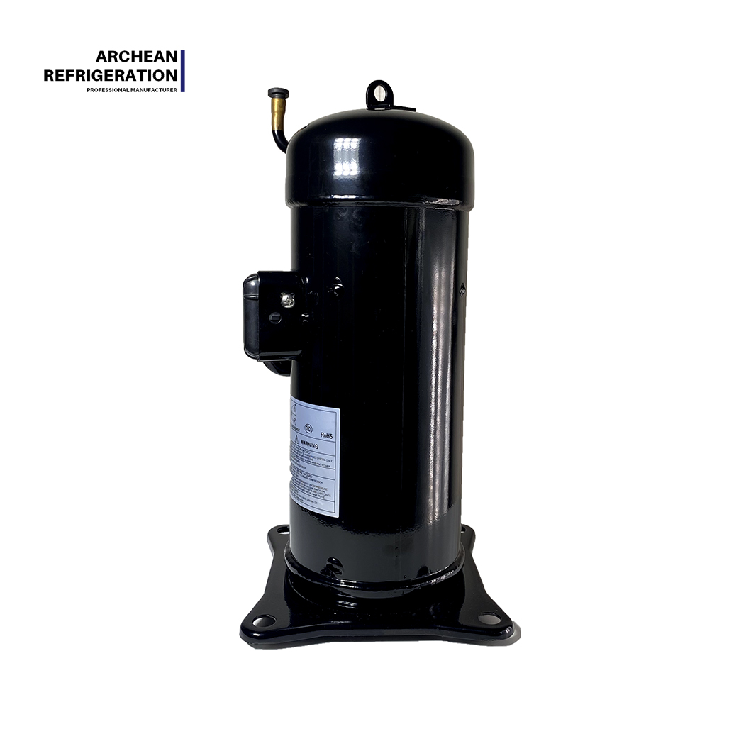
When selecting new equipment, matching the right product parameters to your grid reality is essential. For instance, commercial cooling models operating on a standard 380V-50Hz power supply must feature robust internal motor protection. Scroll compressors, such as the JT90BCBY1L and JT95BCBY1L, are engineered with high-tolerance stators designed to withstand minor transient voltage dips much better than older reciprocating models. For larger tonnage requirements, units like the JT1408CBY1L or JT150BCBY1L provide superior volumetric efficiency. Their advanced scroll compliance allows them to handle the mechanical stress that often accompanies electrical anomalies. Choosing OEM-grade equipment ensures your facility maintains its cooling capacity even when grid conditions fluctuate.
If a system has been punished by unbalanced power for months, the internal damage is usually irreversible. Technicians must perform an insulation resistance test using a Megohmmeter, commonly known as a Megger. By applying a high-voltage DC charge to the windings, the Megger reveals the exact integrity of the insulation. If the readings drop below 20 Megohms, the protective varnish has melted away. The motor is shorting out and is completely beyond field repair.
When a motor is definitively grounded or mechanically seized, replacement is the only logical step to restore business operations. It is crucial to source durable, OEM-equivalent units designed for the rigorous demands of commercial cooling. Upgrading to a high-efficiency model ensures longevity, provided the underlying electrical supply issues have been thoroughly resolved before the new unit is wired in.
Voltage imbalance is a highly destructive, yet often overlooked, electrical anomaly. It stems from a variety of sources, including poorly distributed internal loads, degraded wiring, or unpredictable utility power supply faults. Even a minor percentage of voltage asymmetry translates into massive current imbalance. This leads to severe motor overheating and the premature death of your heavy-duty equipment. By routinely monitoring your electrical supply, balancing your panels, and installing automated phase protection relays, you can safeguard your infrastructure.
Is your facility struggling with repeated cooling failures or burnt-out motors? Do not wait for a catastrophic shutdown. Evaluate your system power quality and upgrade to resilient, commercial-grade solutions. Explore our robust lineup of reliable units, including the JT90BCBY1L and JT150BCBY1L series, at Archean HVAC/R to find the exact match for your 380V-50Hz requirements and get your facility back online safely.
According to industry standards set by the National Electrical Manufacturers Association, the maximum allowable voltage imbalance is 2%. Operating machinery with an imbalance greater than this requires significant motor derating. If the imbalance exceeds 5%, the equipment should be shut down immediately to prevent catastrophic winding failure.
Yes, absolutely. Because a 1% voltage imbalance can cause up to a 10% current imbalance, a system running at a 3% voltage deficit might see one phase drawing 30% more amperage than rated. This massive spike in current easily exceeds the trip curve of standard circuit breakers, leading to continuous nuisance tripping.
It introduces negative sequence voltage, which creates a reverse magnetic field inside the stator. The motor physically fights its own rotation, generating excessive friction and heat. For every 1% of voltage imbalance, internal winding temperatures can surge by roughly 10% to 15%, rapidly baking away the insulation and causing permanent thermal damage.
It can originate from either source, and sometimes both simultaneously. External utility issues include blown grid fuses or uneven transformer tap settings. Internal facility problems typically involve wiring too many single-phase loads, like lighting or computers, to just one phase of the main breaker panel. Proper diagnostic testing will isolate the exact source.
No. Hard start kits are strictly designed to provide extra mechanical starting torque for single-phase motors struggling against high head pressure. They do not alter or correct incoming three-phase electrical supply asymmetry. Resolving an imbalance requires balancing panel loads, replacing degraded contactors, or correcting utility transformer outputs.
Phase loss is essentially the most extreme form of voltage imbalance. It occurs when one of the three phases drops completely to zero volts, usually due to a blown fuse or severed wire. This forces the three-phase motor to run on single-phase power, causing amperage to skyrocket and leading to rapid motor burnout if protection relays do not intervene.
Variable frequency drives can actually be damaged by severely unbalanced input voltage, often leading to DC bus overvoltage faults. However, they are designed to output perfectly balanced voltage to the motor regardless of incoming power flaws. If the drive itself is properly sized and equipped with line reactors, it can act as a buffer to protect the motor from grid instability.


